| Relay Guide
Overview What is a relay? A relay is essentially a switch that is operated electrically rather than mechanically. Although there are various relay designs, the ones most commonly found in low voltage auto and marine applications are electro-mechanical relays that work by activating an electromagnet to pull a set of contacts to make or break a circuit. These are used extensively throughout vehicle electrical systems. Why might I want to use a relay? There are several reasons why you might want or need to use a relay:
This is the most common reason and useful where an in-line switch or the existing circuit does not have the capacity to handle the current required. For example, if you wanted to fit some high power work lights that come on with the headlights but there is a risk that they would exceed the capacity of the existing loom.
High current capacity wiring and switches cost more than lower current capacity versions, so by using relays the requirement for the more expensive components is minimised.
You can use a single input from one part of an electrical system (e.g. central locking output, manual switch etc.) to activate one or more relays that then complete one or more other circuits and so carry out multiple functions from one input signal.
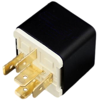
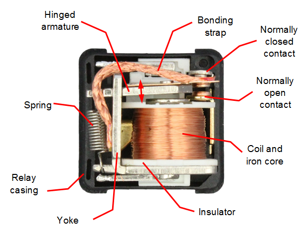
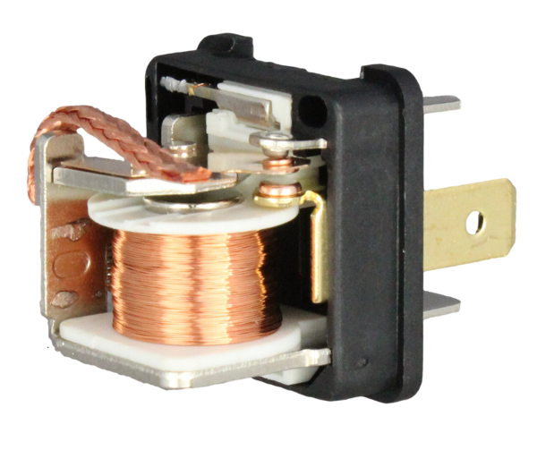
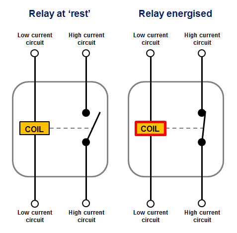
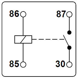
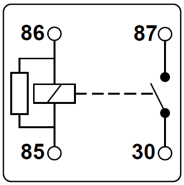
Electromagnetic relays can be put to some quite clever (and complex) applications when linked up to perform logical operations based on certain inputs (for example, latching a +12V output on and off from a momentary input, flashing alternative left and right lights etc.). Although these logical functions have now been superseded by electronic modules for OEM designs, it can still be useful, fun and often more cost effective to use relays to perform them for some after-market projects (particularly where you have a bespoke application). Note: In this article we are going to focus on ISO mini or 'standard' relays which have a 1" cube body and are the most commonly used in vehicle electrical systems. Construction and operation Inside a relay This is what the inside of an ISO mini relay looks like: A copper coil around an iron core (the electromagnet) is held in a frame or 'yoke' from which an armature is hinged. One end of the armature is connected to a tension spring which pulls the other end of the armature up. This is the relay in its de-energised state or 'at rest' with no voltage applied. The braided bonding strap provides a good electrical connection between the armature and yolk, rather than relying on contact between the armature pivot point alone. The coil and contact (or contacts) are then connected to various terminals on the outside of the relay body. How they work When the coil is supplied with voltage a magnetic field is generated around it which pulls the hinged armature down onto the contact. This completes the 'high' current circuit between the terminals and the relay is said to be energised. When voltage is removed from the coil terminal the spring pulls the armature back into it's 'at rest' position and breaks the circuit between the terminals. So by applying or removing power to the coil (the low current circuit) we switch the high current circuit on or off. Note: It is important to understand that the coil circuit and the current-carrying (or switched) circuit are electrically isolated from one another within the relay. The coil circuit simply switches the high current circuit on. The following simplified circuit diagram is often used to easily understand how a relay operates:
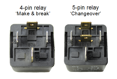
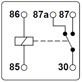
Relay terminology The ISO mini relay we have looked at above has 4 pins (or terminals) on the body and is referred to as a make & break relay because there is one high current circuit and a contact that is either open or closed depending upon whether the relay is at rest or energised. If the contact is broken with the relay at rest then the relay is referred to as Normally Open (NO) and if the contact is closed with the relay at rest then the relay is referred to as Normally Closed (NC). Normally Open relays are the more common type. ISO mini relays with two circuits, one of which is closed when the relay is at rest and the other which is closed when the relay is energised, have 5 pins on the body and are referred to as changeover relays. These have two contacts connected to a common terminal. Make & break relays are also known as Single Pole Single Throw (SPST) and changeover relays as Single Pole Double Throw (SPDT). This is based on standard switch terminology. There are other contact configurations discussed below but make & break and changeover relays are the most commonly used. Terminal numbering convention The terminal numberings found on a relay body are taken from DIN 72552 which is a German automotive industry standard that has been widely adopted and allocates a numeric code to various types of electrical terminals found in vehicles. The terminals on the outside of a 4 or 5 pin mini relay are marked with numbers as shown below:
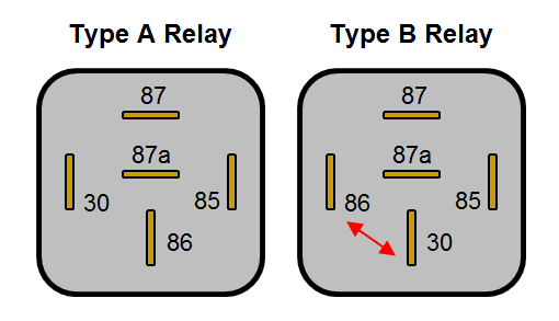
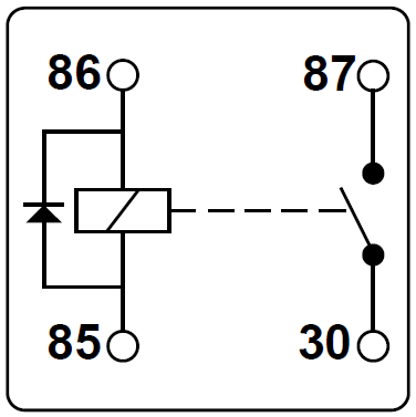
According to DIN 72552 the coil should be fed with +12V to terminal 86 and grounded via terminal 85, however in practice it makes no difference which way around they are wired, unless you are using a relay with an integrated diode (see more info on diodes below). Tip: you can use a changeover relay in place of a make & break relay by just leaving either the NO or NC terminal disconnected (depending on whether you want the circuit to be made or broken when you energise the relay). Terminal layouts The automotive ISO mini relays we have been looking at above are typically available in two types of pin layout designated Type A and Type B layouts. These layouts are shown on the two 5-pin relays below (pin 87a not present on 4 pin relays):
You will notice that on the Type B layout pins 86 and 30 are swapped over compared with the Type A layout. The Type B layout is arguably easier to work with as the connected terminals are in-line, making the wiring easier to visualise. If you need to replace a relay make sure you use one with the same terminal layout as it is easy to overlook if you're not aware of the difference. Terminal sizes The terminal widths used on 4 and 5 pin relays are almost always 6.3mm wide, however some more specialist relays can have terminal widths of 2.8mm, 4.8mm and 9.5mm. The 9.5mm wide terminals tend to be used for higher power applications (such as for starter motor solenoid activation) and the smaller terminals tend to be used for electronics signalling where only very low currents are required. All widths will be compatible with the standard female blade crimp terminals of the corresponding sizes. Relay body markings Relays can look very similar from the outside so they normally have the circuit schematic, voltage rating, current rating and terminal numbers marked on the body to identify them.
This shows the basic internal circuits (including any diodes, resistors etc.) and terminal layout to assist wiring.
The operating voltage of the coil and high current circuits. Typically 12V for passenger vehicles and small craft but also available in 6V for older vehicles and 24V for commercial applications (both auto and marine).
This is the current carrying capacity of the high current circuit(s) and is normally between 25A and 40A, however it is sometimes shown as a dual rating on changeover relays e.g. 30/40A. In the case of dual ratings the normally closed circuit is the lower of the two, so 30A/40A, NC/NO for the example given. The current draw of the coil is not normally shown but is typically 150-200 mA with a corresponding coil resistance of around 80-60 W. Tip: Knowing the coil resistance is useful when testing the relay for a fault with a multi-meter. A very high resistance or open circuit reading can indicate a damaged coil.
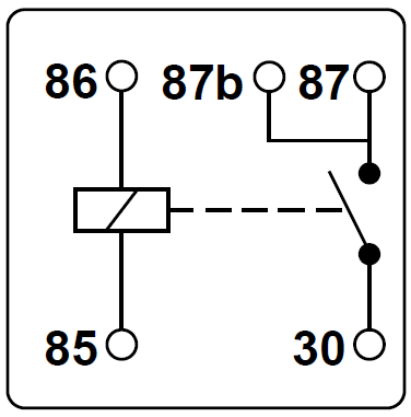
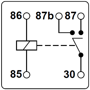
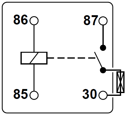
The numbers 85, 86, 30, 87 & 87a (or other numbers for different relay configurations) are normally moulded into the plastic next to each pin and also shown on the circuit schematic. Relay configurations and types In addition to the basic make & break and changeover configurations above, ISO relays are available in a number of other common configurations which are described in the table below:
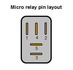
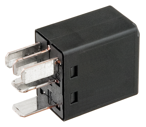
* All schematics shown with the relay at rest (de-energised) Micro relays ISO micro relays are, as the name suggests, smaller than ISO mini relays and designed for use in applications where space is at a premium. They are rectangular in section and narrower than a mini relay with a slightly different pin layout, and are typically available in 'make and break' and 'changeover' configurations, with and without suppression diodes. In addition, the terminal numbering used is sometimes 1, 2, 3, 4 & 5 instead of 30, 85, 86, 87a & 87.
More complex relay types There are other relay designs that are used for some more complex applications in vehicle systems. They are still based upon the principle of switching higher current circuits using smaller current circuits but often combine this with electronics to perform special functions: Some examples are:
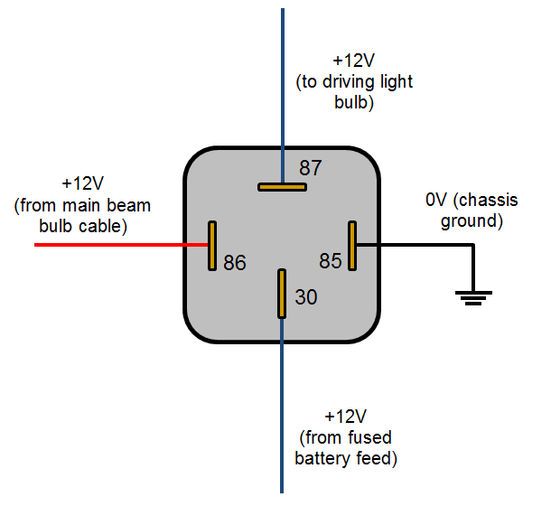
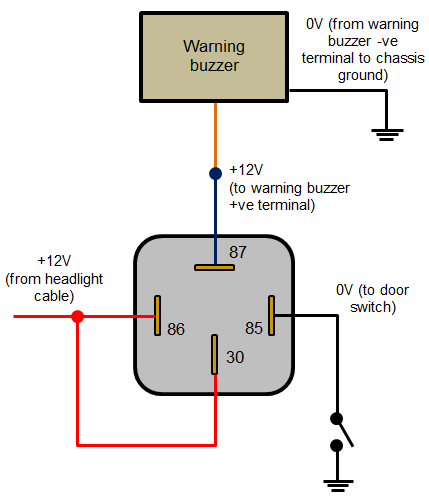
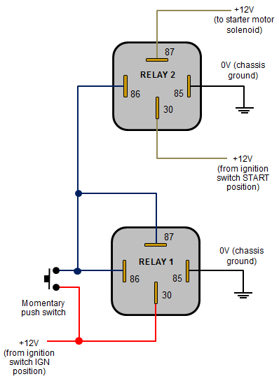
These more complex relays can have up to 9 pins of various sizes. This increase in the number of terminals over the standard 4 or 5 in more simple relays is often necessary because additional connections can be required for the in-built electronics (e.g. inputs from sensors or the ECU and outputs to indicator lights or the ECU). Example relay wiring schemes The following diagrams show some common relay wiring schemes that use 4 pin ISO mini relays.
Disclaimer - The information contained in these articles is provided in good faith and we do our best to ensure that it is accurate and up to date, however, we cannot be held responsible for any damage or loss arising from the use or mis-use of this information or from any errors or omissions. The installer is ultimately responsible for the safety of the system so if you are in any doubt, please consult a qualified electrician. | ||||||||||||||||||||||||||||||||||||||||||||||||||||||||||||||||||||||||||||


 Customer Services Customer Help Contact
© 2024 12 Volt Planet Ltd. All Rights Reserved. Company Reg no. 8239412 |


12 Volt PlanetAuto & Marine Electrical Components |