| Fusing Guide
Overview Fuses are critical in any electrical system and are used to protect a circuit's cabling from excessive current that could lead to damage and, very often, an electrical fire. Excessive current is most likely to be caused by three things:
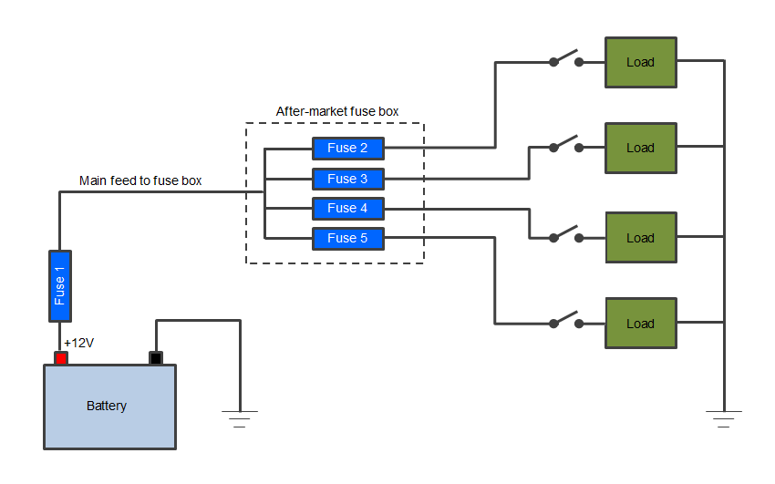
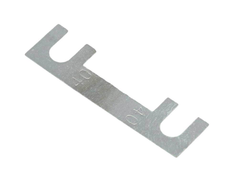
Where and when to use fuses In an ideal world each individual section of positive cable would be fused as this would provide the most protection and make fault finding relatively straight forward, because it would allow you to narrow down the problem to a single section of cable (i.e. where the fuse has blown). Having said that this is ideal it is nearly always impractical as it would lead to many fuses fitted throughout an electrical system. A good compromise is that every individual circuit should be fused as this provides a good degree of protection and at least allows you to narrow down the problem to one circuit. It is important to note that the section of cable coming from the battery +ve terminal to the first fuse (or battery distribution box) is effectively an unprotected part of the circuit. If there is a short anywhere along this length then it is very likely to catch fire as the first fuse will not experience the excess current. For this reason the length of cable from the battery +ve to the first fuse should be as short as possible so that damage is minimised in the event of an electrical fire. Fusing Exceptions There are some instances where fuses are not normally used and one example is for the, normally short, length of cable from the battery to the starter motor. Starter motors are normally the highest current draw electrical item on a vehicle as they have to crank the engine, and the current can reach several hundred Amps, especially with large diesel engines that have a high compression ratio. For this reason it is usually deemed impractical to fuse this length of cable, although some vehicles do have fusible links which are simply a small section of lower current rating cable encased in a fireproof sleeve. They are installed with the cable being protected and are designed to melt and break the circuit in an over-current condition. The other reason for not fusing the starter circuit is that if the battery is disconnected from the alternator whilst it is turning (as would be the case if a fuse blew) the diodes in the alternator's rectifier can be damaged. To offer an increased level of safety it is common in many race car, kit car, custom car and leisure vehicle builds to fit a battery cut-off or master switch that can be manually operated to isolate the main battery or auxiliary batteries from the rest of the vehicle's electrical system in the event of a problem. Typical after-market fusing arrangement The following diagram shows how electrical loads such as lights etc. might be fused in an after-market circuit.
Note that the main feed from the battery is fused to protect this section of cable and this cable should be large enough to supply the current required by all the loads operating at the same time (worst case). Consequently the fuse used for this cable (fuse 1) will be of a higher rating than fuses 2-5 (see below for selecting a fuse rating). Each of the four circuits supplying the loads are then fused individually in the fuse box at the beginning of each circuit (and before the switches). This is important because if a section of cable shorts to ground it will only be protected if there is a fuse before the shorting point (otherwise the fuse will not experience the excess current because it will be outside of the short-circuit). Fuse ratings
In simplified terms the greater the current is above the continuous rating, the faster the fuse will blow. For example, if a 10A fuse is exposed to 11A then it might take many minutes for it to blow but if it is exposed to 20A then it may blow in a fraction of a second. Manufacturers show this blow time on a Current-Time chart but for the typical user it's not necessary to go into this level of technical detail as long as you follow some basic fuse selection guidelines as described in the next section: Selecting the correct fuse rating If replacing a blown fuse in a manufacturer-designed (factory) application, e.g. in a vehicle fuse panel, then the same type and rating of fuse should be used. If a fuse continues to blow then there must be a fault with the circuit and a higher rating fuse should never be fitted to overcome this, even temporarily. Doing this creates a high risk of component failure and electrical fire. When specifying a fuse for an after-market application, the key consideration is that the fuse should be the weakest point (i.e. lowest rated component) so that it always blows before any damage occurs to other parts of the electrical circuit. However, you also do not want the fuse to keep blowing under normal operation (known as a nuisance blow), so the two elements to consider are:
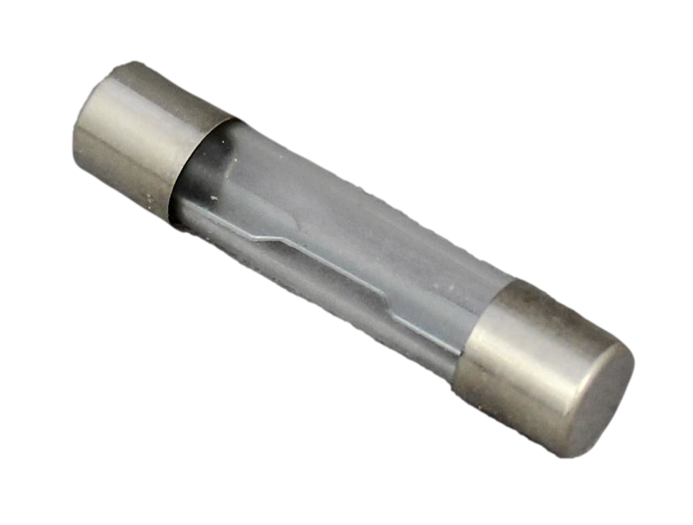
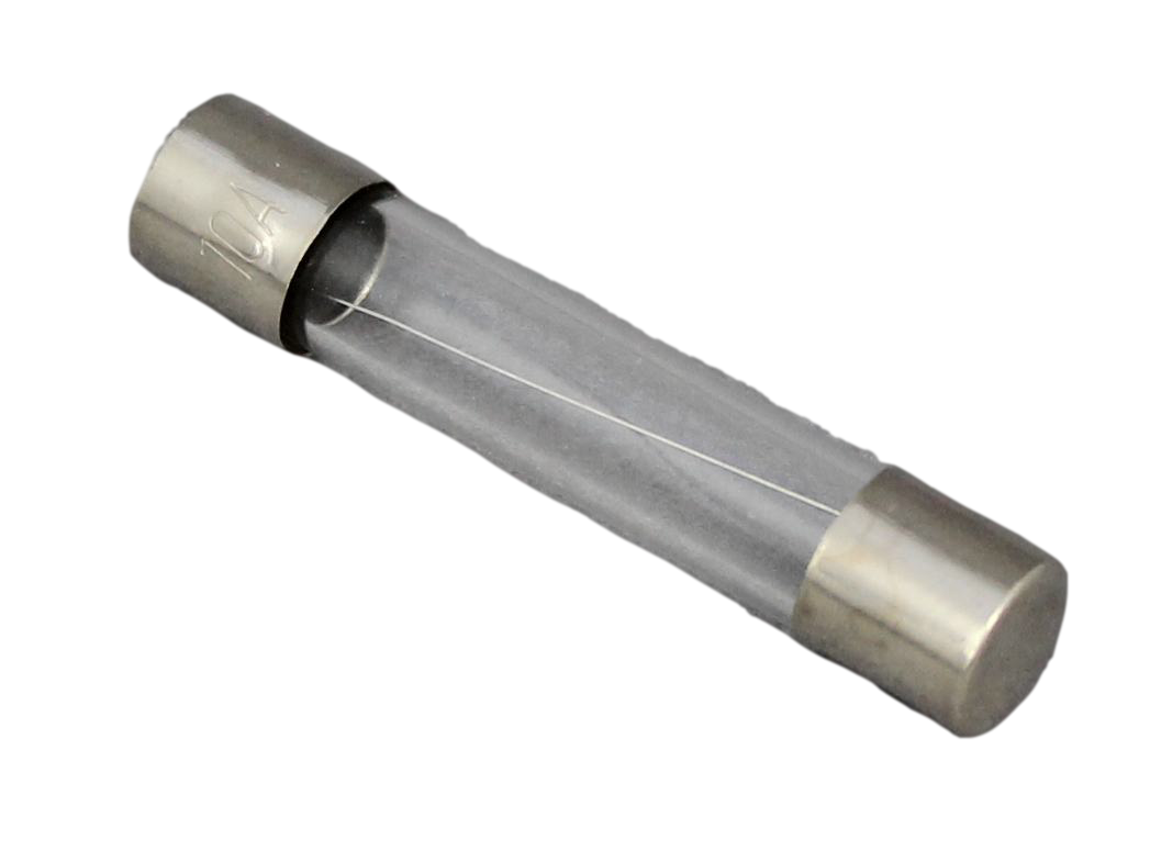
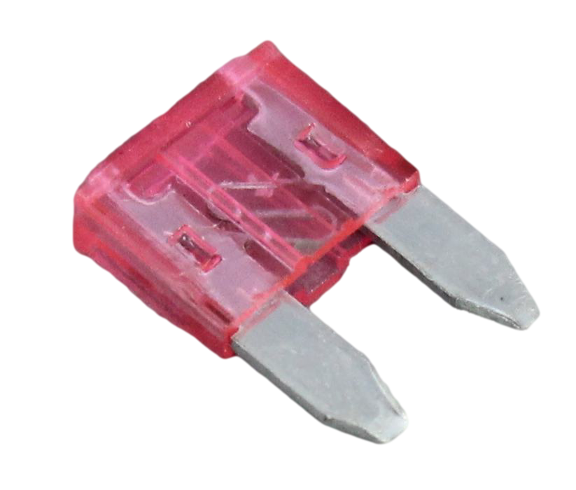
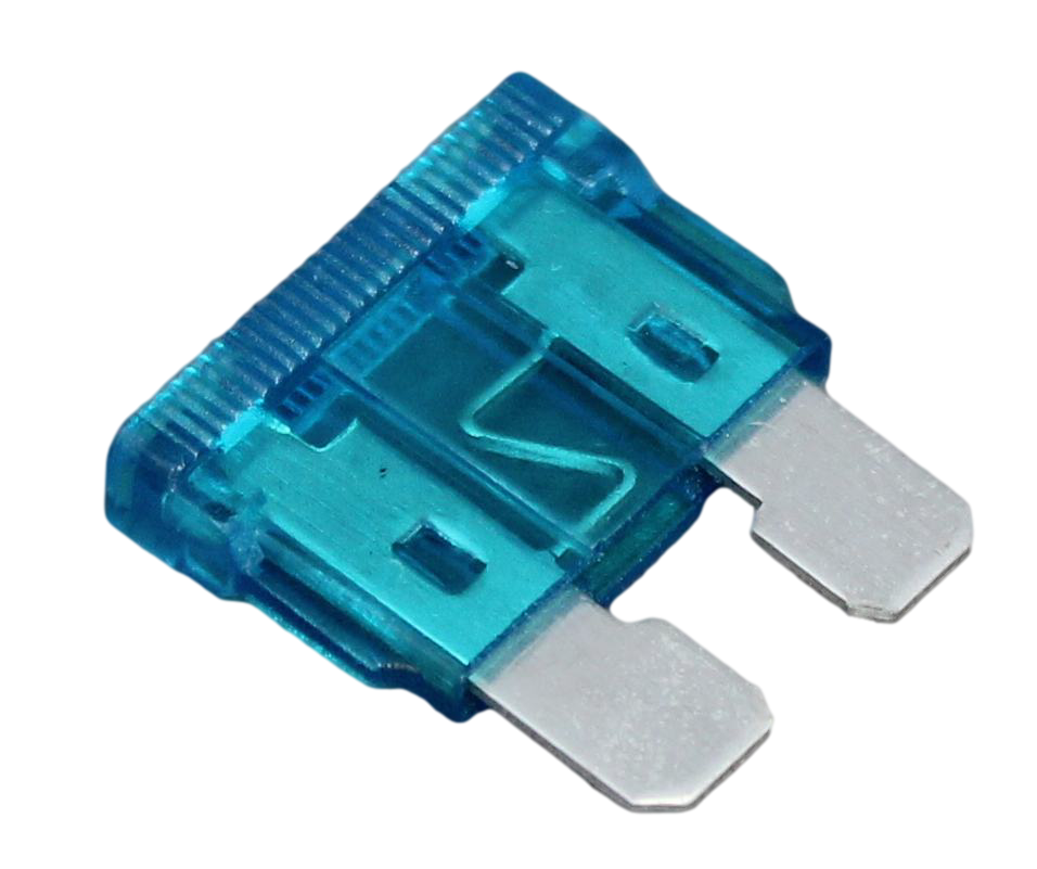
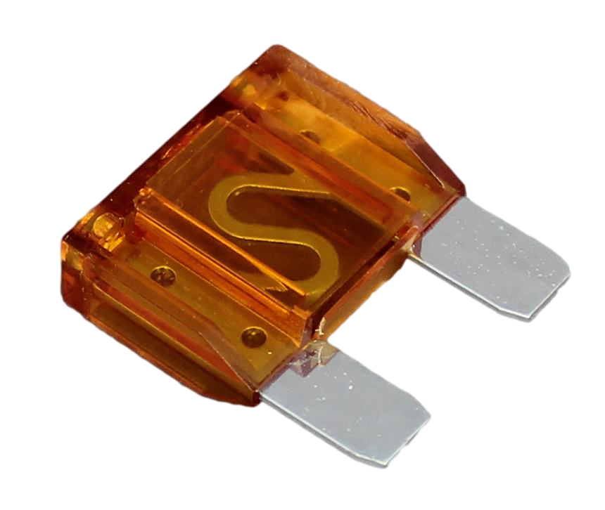
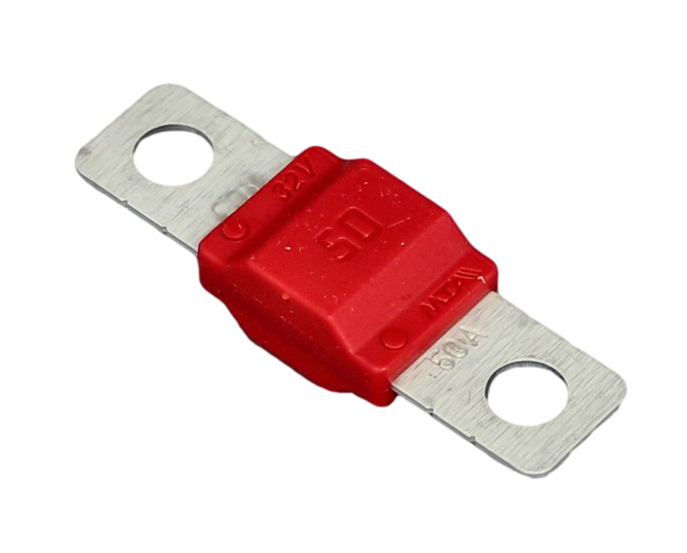
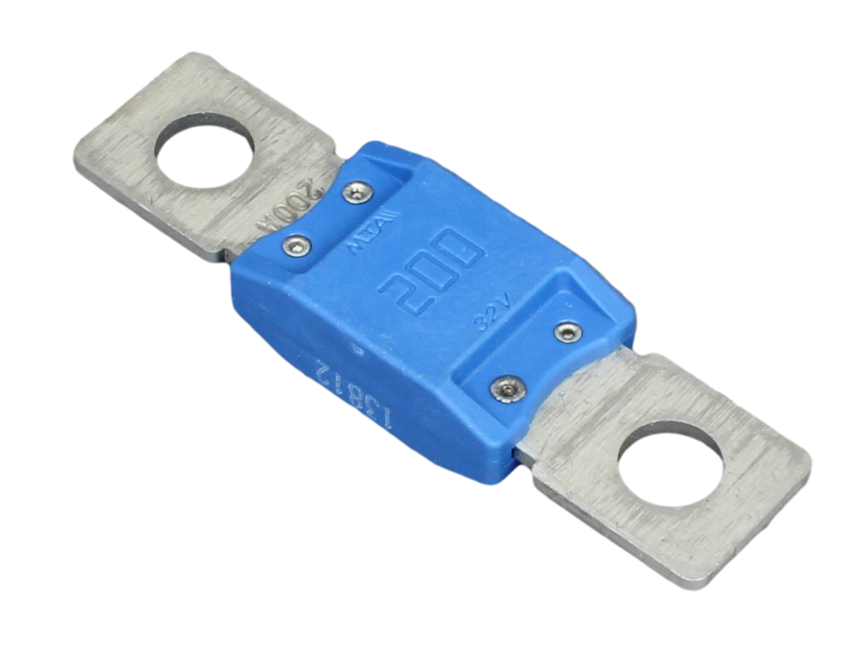
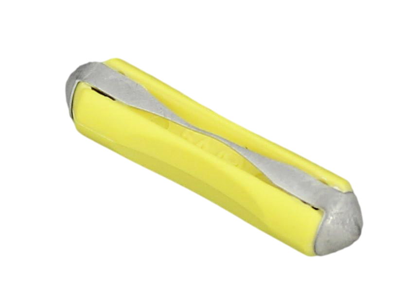
>The fuse rating should lie somewhere between these two values to allow normal operation but blow on overload. For example, if the normal expected current draw is 10A and the cable size is 25A, then a fuse rated at 15A would be appropriate. Types of Fuse There are several types of fuse currently in use in the automotive market and the table below gives a brief description of each:
Circuit Breakers What is a circuit breaker? Circuit breakersprovide overload protection for the circuit in the same way that a fuse does (by breaking the circuit continuity) but, unlike a fuse, can be reset rather than having to be replaced. These are useful in applications where, due to their nature, an over-current condition is expected to occur now and again under normal use and to have to frequently replace fuses would be inconvenient (e.g. electric motors used for winches, power windows etc.). They are also useful where you might need to reset the circuit quickly and don't want to spend time looking for a fuse. How do they work? Most circuit breakers found in 12V or 24V systems operate thermally. The heat generated by the excess current during an overload causes the contacts inside the breaker to come apart and break the circuit. These are then reset either manually or automatically depending on the design of the circuit breaker. Circuit breakers that have to be manually reset provide an opportunity to check for any problems before using the circuit again and on some types you can manually trip the breaker, which is useful for isolating the circuit and for testing the breaker. Fuses vs circuit breakers Whilst circuit breakers are very useful solution in certain applications it should be noted that a good quality fuse will ultimately be more reliable (there are no moving parts) so should be considered first, and where sensitive electronic equipment is involved a circuit breaker should never be used. This is because the time taken for the circuit breaker to operate can be longer than it would take a traditional fuse to blow, potentially exposing the circuit to damaging overload currents for longer. Disclaimer - The information contained in these articles is provided in good faith and we do our best to ensure that it is accurate and up to date, however, we cannot be held responsible for any damage or loss arising from the use or mis-use of this information or from any errors or omissions. The installer is ultimately responsible for the safety of the system so if you are in any doubt, please consult a qualified electrician. |


 Customer Services Customer Help Contact
© 2024 12 Volt Planet Ltd. All Rights Reserved. Company Reg no. 8239412 |


12 Volt PlanetAuto & Marine Electrical Components |