| Electrical Circuit Basics
Electricity is a fundamental part of the workings of most vehicles and this section aims to explain the basic principles of electrical circuits. Hopefully this will give you an understanding and allow you to carry out some simple calculations for specifying the electrics in your auto or marine wiring projects.
The fundamentals of an electrical circuit In its most simple form, an electrical circuit consists of three fundamental parts:
The conductor is used to connect the positive side of the power source to the load which is then connected back to the negative side of the power source to complete the circuit. A current will then flow through the load, converting stored energy in the battery to another form. Describing the workings of an electrical circuit These terms are commonly used when describing electrical circuits:
It's often helpful to understand these concepts by using the analogy of a plumbing system:
Watts is a universal measurement of energy conversion (or 'work done') so it applies equally to water systems as it does to electrical systems. A garden sprinkler will have 'power' due to the rate at which it converts the energy in the water into energy to rotate, just as a bulb will have a power as it converts electrical energy into light and heat. This analogy can also be continued when we think about changing these values:
Current and current flow The type of current utilised in the running of vehicle electrical systems is Direct Current (DC) where the flow of charge is in one direction and the voltage level is constant. Alternating Current (AC), as used in households where the flow of charge is in both directions and the voltage changes with time, is produced by the vehicle's alternator but is converted by a set of diodes (the rectifier) into DC which is then used to charge the battery. The conventional way of thinking about current flow in a circuit is that it flows from the positive terminal of the battery to the negative terminal (or ground). Current flow is the movement of free electrons within the conductor and since electrons are negatively charged they actually migrate towards the +ve terminal of the battery when subject to a voltage difference, so current flow is from -ve to +ve.
This concept is fairly counter-intuitive for most people and so the convention of current flow being from +ve to -ve has stuck, and it makes little practical difference.
The relationship between Volts, Amps, Ohms & Watts The relationship between these various terms is described in two very simple equations, allowing you to calculate any unknown value as long as you know the 2 other values.
For a given power requirement, a higher voltage will require fewer amps and vice versa. This is the reason that circuits operating at 12V DC can produce much higher currents than would be experienced in household AC circuits that operate at 240V AC. The following diagram is a handy visual reference showing all of the possible arrangements of the above equations that you might need to work out the unknown value:
One of the most common uses of the above equations is for calculating the current drawn by a load (bulb, heating element, motor etc.) so you can select a suitable size cable for a circuit. It can be seen from the above that this arrangement is: So for example, if we wanted to wire up a light that we know has a power rating of 50W, then the current draw would be 50W/12V = 4.17A. This tells you that you could use a cable with a rating of 4.17A or above, however it is good practice not to design a circuit operating at the upper end of the cable's rating and so you should select a cable with some additional capacity. In this case 0.5mm² (11A) cable would be appropriate. This specific re-arrangement of Watt's Law is worth remembering as it comes in useful again and again when determining an appropriate size cable to use. Ground In order for an electrical circuit to be complete the positive terminal of the battery must be connected through the loads and back to the negative terminal, otherwise current cannot flow. In automotive vehicles the negative terminal of the battery is very often connected to the metal chassis which is a good conductor and effectively makes the entire chassis (and body of the vehicle, if metallic) a common ground point. The chassis can then be thought of as a large extension of the negative battery terminal and proves very convenient for grounding different parts of the electrical system, as there is normally a suitable chassis (or body) location close by to complete the circuit. This is only possible because of the use of rubber tyres which virtually insulate the vehicle from earth, preventing current leakage. In fact tyres do conduct slightly due to the carbon content in the rubber which helps remove static build-up, but the resistance is relatively high and so the effect on the electrical system very small. In marine craft the hull is more often than not of a fibre glass (GRP) or wooden construction, materials which are not electrically conductive and so not suitable as a common ground point. Even if they were conductive (e.g. some boats have steel hulls) this is still not suitable as the hull would have a connection with the seawater surrounding it (an excellent conductor) which would provide a current leakage path to earth. So in marine craft all circuits must return to the negative battery terminal to complete the circuit. In practice this is achieved by having busbars (common ground connections) at various locations in the craft to provide conveniently sited ground return points to consolidate many individual circuits. Negative and Positive Ground In older vehicles it was common for the chassis to be connected to the +ve terminal of the battery (known as a positive ground), however this was superseded by the negative ground we are familiar with today. This does not affect simple devices such as bulbs and fuses which are not sensitive to polarity, but can be a problem for some equipment such as gauges, senders and electronics, so many people restoring classic cars opt to have their electrical system converted to negative ground for convenience. Disclaimer - The information contained in these articles is provided in good faith and we do our best to ensure that it is accurate and up to date, however, we cannot be held responsible for any damage or loss arising from the use or mis-use of this information or from any errors or omissions. The installer is ultimately responsible for the safety of the system so if you are in any doubt, please consult a qualified electrician. |


.png) Overview
Overview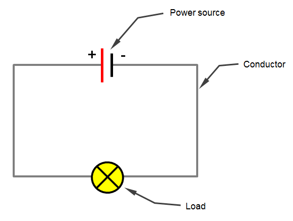


 Customer Services Customer Help Contact
© 2024 12 Volt Planet Ltd. All Rights Reserved. Company Reg no. 8239412 |


12 Volt PlanetAuto & Marine Electrical Components |