| Cable Sizing & Selection
One of the most important aspects of designing and building any part of a vehicle electrical system is determining the correct size and type of cable to use for each circuit. Too small a cable size and you'll run the risk of generating heat in the cable; too large and you'll be wasting money on copper you don't need. Also, what sort should you use - plain copper or tinned, standard PVC insulation or thinwall insulation? The following article should give you an insight into how electrical cable is specified and allow to you choose the right one for your application. For a brief look at how to select the best cable for you check out our YouTube Video Cable construction You will have noticed that cable used in vehicle electrical systems is very flexible in contrast to the cable you would find in the the walls of your home, which is fairly stiff. The reason for this is that copper, although quite ductile, is susceptible to 'work hardening' when subject to vibration and mechanical shock, such as is experienced when installed in a vehicle. This work hardening causes the metal to become more brittle which could, over a long period of time, cause a stiff, solid conductor to crack and fail. This problem is overcome by manufacturing the core from many small diameter strands of copper wire to make up the desired cross-sectional area, rather than using a single wire. This type of cable is (unsurprisingly) known as 'stranded' cable and provides much more flexibility, which means improved resistance to work hardening making it better suited to use in vehicles. The difference in cross sections is shown in the diagram below:
Tip: Be careful when stripping the insulation from a stranded cable that you don't accidentally remove any of the copper strands. This will reduce the total cross-sectional area of the conductor at that point and consequently also reduce the current carrying capacity of the cable. The same applies when crimping the conductor to a terminal - make sure all strands are contained within the crimp or the current carrying capacity will be reduced. Cable specifications Cables are generally specified using the following properties:
Additional specifications may include a working temperature range and resistance to certain chemicals such as acids, fuels, oils etc. Selecting cable The following are some points you should consider when selecting cable for a particular application: 1. Current carrying capacity Each component or appliance connected to a circuit will have a current draw associated with its operation and it is important that the cable supplying power to these is capable of carrying the normally expected current, plus a margin of safety. If it is not capable then it is likely to result in the cable becoming hot and potentially catching fire. Although fuses are used in the circuit to protect the cable, the cable itself should be of an adequate rating to prevent this over-heating occurring under normal circumstances. You might find it useful to read our Electrical Circuit Basics article for using the equation I = P/V where the following example is given: If we wanted to wire up a light that we know has a power rating of 50W, then using I = P/V the current draw would be 50W/12V = 4.17A. This tells you that you could use a cable with a rating of 4.17A or above, however it is good practice not to design a circuit operating at the upper end of the cable's rating and so you should select a cable with some additional capacity. In this case 0.5mm² (11A) cable would be appropriate. 2. Voltage drop All elements of an electrical circuit have resistance, including electrical cable, which means that there will be energy loss in the form of voltage drop experienced along the length of the cable. Just as a bulb converts electrical energy into heat and light due to its resistance, and so induces a voltage drop, a copper conductor has resistance and will convert some of the energy it conducts, causing a voltage drop in the same way. The difference is that voltage drop across a bulb (or other load) is useful as that's what makes it work, but voltage drop along cable and other passive parts of a circuit is not desirable as it's not a useful conversion of energy. In low voltage systems cable length can have a significant impact on voltage drop. Even a cable run of a few metres for small cross-section conductors can produce significant voltage drops and this problem is demonstrated well on some vehicles where the headlights are not as bright as they could be. If you check the voltage at the bulb connectors you might find that the bulbs are not receiving a full 12V from the circuit due to the conductor size being too small for the cable run length. Some owners opt to improve their headlight circuit by using cable with a larger conductor over a shorter distance which allows the circuit to provide full voltage to the bulbs, often with very significant improvements in lighting brightness. So we want to select a cable to make sure that the voltage drop is not so large that it will cause problems, but what is acceptable and how do we calculate the right cable size to use? Well the generally acceptable voltage drop for DC circuits is around 3-4% and we can use V = IR (see Electrical Circuit Basics ) to calculate the voltage drop for a cable if we know the current draw of the load and the cable's resistance per metre. Example Using the above example of a 50W light we now know it draws 4.17A, so if we were to use a 0.5mm² cable which has a resistance of 0.037 Ω/m and its total length from battery positive back to battery negative was 5m, then the voltage drop would be: Vdrop = IR = 4.17A x (5m x 0.0371Ω/m) = 0.774V or 6.45% This shows that although 0.5mm² cable is OK for the expected current draw of the light, it's not OK for the cable run length as the drop is greater than 3%. So what about 1.5mm² cable with a resistance of 0.013 Ω/m? Vdrop = IR = 4.17A x (5m x 0.0127Ω/m) = 0.265V or 2.21% This shows that 1.5mm² cable (at a current rating of 21A) will be suitable for the cable run length as the drop is well under 3% There is a general rule of thumb that says if you're unsure whether the cable is large enough for the job, go up a size. This is a bit crude and not very scientific but it's not a bad rule to apply as increasing cable size can't do any harm. Anyway, enough maths - to make it easy we've developed this handy calculator which will show you the approximate voltage drop based on cable size, supply voltage, current draw and cable length. Voltage Drop Calculator
Generally acceptable max. voltage drop is around 3-4% It is important to note that voltage drop occurs not only along the positive cable to the load but also along the negative return cable. When you enter the cable length as the 'one-way' distance to the load the calculator assumes (for simplification) that the return distance is identical, giving you a total cable length which is twice that of your entered value. In practice your return cable length might be much shorter as it will may be grounded to a nearby point on the chassis (at least in vehicles) , so the remainder of the distance back to the battery negative should have an extremely low resistance relative to a cable. In this case the actual voltage drop would probably be less than calculated, but it provides a 'worst case' figure to work with. Voltage drop can also be caused by high temperatures, although to a lesser degree than cable length, because as temperature increases, resistance increases and vice versa. In high voltage systems voltage drop is not such an issue which is one of the reasons why electrical cables running many miles are operating at hundreds of KV. The other reason is that the same power can be delivered at a higher voltage but with a lower current, meaning that smaller sized, less expensive cable can be used. 3. Materials Low voltage automotive and marine cable is available in different materials/constructions and the following table gives a brief overview:
4. Summary So in selecting your cable you need to make sure that:
Get these right and you can be confident that your cable is right for the job! AWG to Metric Cable Size Conversion In Europe, metric sizes are used for stranded cableand are expressed as the total cross sectional area of the conductors together with the number of strands and their diameter. For example, a cable specified as 2.0mm² 28/0.30 indicates that it has a total conductor cross sectional area of 2.0mm² and is made up of 28 individual strands, each of 0.3mm diameter. In North America the AWG standard is most commonly used for stranded cable and expresses the Gauge together with the number of strands and their Gauge. For example, a cable specified as 16 AWG 7/24 has a size of 16AWG and is made up of 7 individual strands, each of 24 AWG. The table below provides a cross-reference between these two standards, showing the closest metric equivalents to each Gauge for cable sizes commonly used in low voltage automotive and marine applications.
Disclaimer - The information contained in these articles is provided in good faith and we do our best to ensure that it is accurate and up to date, however, we cannot be held responsible for any damage or loss arising from the use or mis-use of this information or from any errors or omissions. The installer is ultimately responsible for the safety of the system so if you are in any doubt, please consult a qualified electrician. | |||||||||||||||||||||||||||||||||||||||||||||||||||||||||||||||||||||||||||||||||||||||||||||||||||||||||||||||||||||||||


.png) Overview
Overview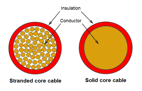
 Customer Services Customer Help Contact
© 2024 12 Volt Planet Ltd. All Rights Reserved. Company Reg no. 8239412 |


12 Volt PlanetAuto & Marine Electrical Components |